Gerber Beam
Categories: Lab EquipmentLines of Influence on the Gerber Beam Technical Description: Many bridges are executed as Gerber beams. Bridges are subjected to moving loads. Consequently, it is important to take these moving loads...
Product
Description
Lines of Influence on the Gerber Beam
Technical Description:
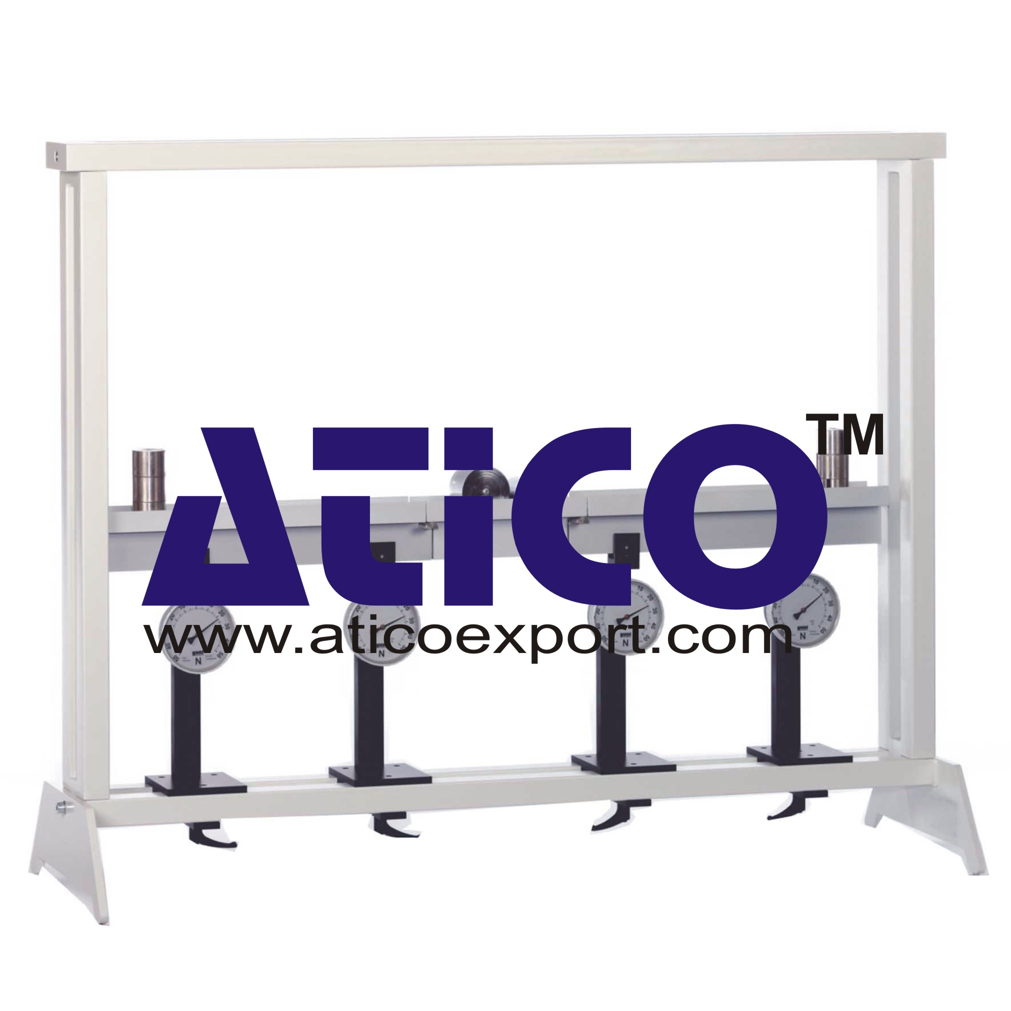
Many bridges are executed as Gerber beams. Bridges are subjected to moving loads. Consequently, it is important to take these moving loads into account in the design process. To that end, the so-called lines of influence are determined. Lines of influence describe static reactions to a moving load, such as the internal reactions of the beam or support reactions. The lines of influence are determined by way of method of sections and the conditions of equilibrium, in the same way as the bending moment diagram for a static load for example. A Gerber beam is an articulated beam, in the case of Gerber Beam with two cantilever beams and a suspended beam between them. Two bearings support each cantilever beam. The suspended beam is mounted on articulated supports on each of the cantilever beam arms. As a result the entire beam is statically determinate. The cantilever beam supports are equipped with force gauges which indicate the support reactions. Single weights and a moving load are provided to place load on the beam. This means the beam can be subjected to point or distributed loads, or to a moving load. The force gauges indicate the effect of a moving load directly in the support reactions. The supports are movable. The various elements of the experiment are clearly laid-out and housed securely in a storage system. The complete experimental set-up is arranged in the frame.
Specification:
1. Investigation of the lines of influence in a statically determinate Gerber beam under different loading 2. Beam comprising 2 cantilever beams and 1 suspended beam 3. Suspended beam mounted by articulated supports on cantilever beams 4. Beam subjected to moving load or loaded down by single weights 5. 4 movable supports with force gauge 6. Storage system to house the components 7. Experimental set-up in frame.Technical Data:
Beam
- total length: 1220mm - cantilever beam length: 503mm - suspended beam length: 250mm - gauge: -50...+50N
Weights
- 24x 5N - 12x 1N - moving load: 10+20N
quick overview :
Lines of Influence on the Gerber Beam
Technical Description:
Many bridges are executed as Gerber beams. Bridges are subjected to moving loads. Consequently, it is important to take these moving loads into account in the design process. To that end, the so-called lines of influence are determined. Lines of influence describe static reactions to a moving load, such as the internal reactions of the beam or support reactions. The lines of influence are determined by way of method of sections and the conditions of equilibrium, in the same way as the bending moment diagram for a static load for example. A Gerber beam is an articulated beam, in the case of Gerber Beam with two cantilever beams and a suspended beam between them. Two bearings support each cantilever beam. The suspended beam is mounted on articulated supports on each of the cantilever beam arms. As a result the entire beam is statically determinate. The cantilever beam supports are equipped with force gauges which indicate the support reactions. Single weights and a moving load are provided to place load on the beam. This means the beam can be subjected to point or distributed loads, or to a moving load. The force gauges indicate the effect of a moving load directly in the support reactions. The supports are movable. The various elements of the experiment are clearly laid-out and housed securely in a storage system. The complete experimental set-up is arranged in the frame.
Specification:
1. Investigation of the lines of influence in a statically determinate Gerber beam under different loading 2. Beam comprising 2 cantilever beams and 1 suspended beam 3. Suspended beam mounted by articulated supports on cantilever beams 4. Beam subjected to moving load or loaded down by single weights 5. 4 movable supports with force gauge 6. Storage system to house the components 7. Experimental set-up in frame.Technical Data:
Beam
- total length: 1220mm - cantilever beam length: 503mm - suspended beam length: 250mm - gauge: -50...+50N
Weights
- 24x 5N - 12x 1N - moving load: 10+20N
Product
Reviews
add Review
reviews
No Review Yet.





Product
Reviews
add Review
reviews
No Review Yet.