Refrigeration Cycle Demonstration Equipment
Categories:Refrigeration Cycle Demonstration Equipment Teaching Objectives of Refrigeration Cycle Demonstration Equipment Observe the evaporation and condensation of the refrigerant. Represent and understan...
Product
Description
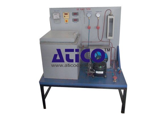
Refrigeration Cycle Demonstration Equipment
Teaching Objectives of
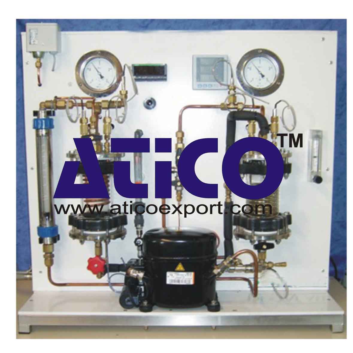
Refrigeration Cycle Demonstration Equipment- Observe the evaporation and condensation of the refrigerant.
- Represent and understand the refrigeration cycle in a diagram: log p,h.
Energy Balances
- Determination of the coefficient of performance
- Oil return in a submerged evaporator
Technical specifications
- An evaporator in which the coolant is vaporized and removes a certain quantity of heat from the water circulating in the copper tube coil.
- A hermetic compressor.
- A condenser.
- A pressure relief valve that allows the passage of coolant, liquid from the condenser, towards the evaporator by reducing pressure.
- A porthole window placed between the pressure relief valve and the evaporator allows observation of steam formation during the period of rest.
Instrumentation
- Two pressure gauges.
- Eight Pt100 sensors with a digital indicator
- Two flowmeters
Supplementary
- Option 1: Digital Wattmeter
- Option 2: Rotameter for the coolant flow rate
- Option 3: Acquisition module:
- Replacement of two gauges by piezometric sensors with analog output
- Interfaces 4-20 mA / RS485
- RS485 Converter - RS 432
- One OPC server
- Block diagram of the system developed in Labview
Essential requirements
- Electricity supply: 220/240 V single phase 50 Hz + Earth
- Water supply and drainage: 400 L/h, pressure 1 bar
Dimensions and weight
- 850 x 550 x 800mm – 50 kg
quick overview :
Refrigeration Cycle Demonstration Equipment
Teaching Objectives of
Refrigeration Cycle Demonstration Equipment- Observe the evaporation and condensation of the refrigerant.
- Represent and understand the refrigeration cycle in a diagram: log p,h.
Energy Balances
- Determination of the coefficient of performance
- Oil return in a submerged evaporator
Technical specifications
- An evaporator in which the coolant is vaporized and removes a certain quantity of heat from the water circulating in the copper tube coil.
- A hermetic compressor.
- A condenser.
- A pressure relief valve that allows the passage of coolant, liquid from the condenser, towards the evaporator by reducing pressure.
- A porthole window placed between the pressure relief valve and the evaporator allows observation of steam formation during the period of rest.
Instrumentation
- Two pressure gauges.
- Eight Pt100 sensors with a digital indicator
- Two flowmeters
Supplementary
- Option 1: Digital Wattmeter
- Option 2: Rotameter for the coolant flow rate
- Option 3: Acquisition module:
- Replacement of two gauges by piezometric sensors with analog output
- Interfaces 4-20 mA / RS485
- RS485 Converter - RS 432
- One OPC server
- Block diagram of the system developed in Labview
Essential requirements
- Electricity supply: 220/240 V single phase 50 Hz + Earth
- Water supply and drainage: 400 L/h, pressure 1 bar
Dimensions and weight
- 850 x 550 x 800mm – 50 kg
Product
Reviews
add Review
reviews
No Review Yet.




Product
Reviews
add Review
reviews
No Review Yet.