Strain Bridge
Categories: Mechanical Lab Equipment ManufacturerStrain Bridge Strain Bridge has high-contrast digital display gives a direct reading in micro-strains, for half or full bridge operation of the six channels. Measurements with a quarter bridge configu...
Product
Description
Strain Bridge
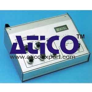
Strain Bridge has high-contrast digital display gives a direct reading in micro-strains, for half or full bridge operation of the six channels. Measurements with a quarter bridge configuration can be made by adding a resistor. The gauge factor can be adjusted between 1 and 5. Each channel can be balanced separately by means of multiturn potentiometers. An analogue output for each channel permits the display of the signals using an oscilloscope or a plotter, and also data acquisition. With the bridge energisation of 2.5 V, strain gauges of 120 W minimum can be used. These can be in Constantan, Isoelastic Karma or Platinum - Tungsten alloys. The 20 000 point digital display allows measurements in the range ± 20 000 mm/m, whatever the gauge alloy.
Technical specifications
- Number of channels: 6.
- Operating range: ± 20 000 µm/m.
- Resolution: ± 1 µm/m.
- Bridge energisation: 2.5 V - Stability: 10-4.
- Gauge configuration: Full or half bridge with gauges of 120 to 5000 WQuarter bridge with additional resistor.
- Input impedance: 1010 W.
- Balance: using multi-turn potentiometers ± 2000 µW/W.
- Gauge factor read directly on display adjustable from 1 to 5 by multi-turn locking potentimeters.resolution: 0.001.
- Amplifier: precision 1 %.
- linearity: ± 0.002 %drift: 0.25µV/°C noise: less than 13µV per Hzcommon mode rejection:< 100 dB.
- Analogue outputs: independant output for the 6 channels, using Cannon 9 pin connectors max. output voltage: 10 V band pass: 0 - 10 kHz.
- 2 V for 20000 µW/W.
- Minimal load: 22000 W.
- Gauge connections: 15 pin Cannon connectors way rapid connector.
Option :
- Data acquisition and processing with an IBM-PC or compatible micro-computer, the system can configure and read the six channels simultaneously. It comprises three elements:
Software package
Allows for each series of measurements :- Test identification.
- Strain bridge initialisation.
- Channel selection, gain, configuration (full or half-bridge), gauge factor, graph configuration, sampling rate, total number of acquisitions.
- Visualisation.
- Safeguard.
- Print-out.
- Saving test to file.
- Card-bridge connecting cable.
- Analogue / Digital acquisition card.
Features :
- Reads 16 single analogue inputs or 8 differential analogue inputs.
- 12 bit digital conversion, or a resolution of 4096 points full scale.
- Accepts maximum voltages of 0 to 10 volts in unipolar mode and ± 5 volts in bi-polar mode.
- Fixed frequency acquisition, through built-in time
Dimensions and weight
- 265 x 105 x 84 mm.
- Net weight : 1.8 Kg.
Essential requirements
- Voltage : 220 V, 50 or 60 Hz
quick overview :
Strain Bridge
Strain Bridge has high-contrast digital display gives a direct reading in micro-strains, for half or full bridge operation of the six channels. Measurements with a quarter bridge configuration can be made by adding a resistor. The gauge factor can be adjusted between 1 and 5. Each channel can be balanced separately by means of multiturn potentiometers. An analogue output for each channel permits the display of the signals using an oscilloscope or a plotter, and also data acquisition. With the bridge energisation of 2.5 V, strain gauges of 120 W minimum can be used. These can be in Constantan, Isoelastic Karma or Platinum - Tungsten alloys. The 20 000 point digital display allows measurements in the range ± 20 000 mm/m, whatever the gauge alloy.
Technical specifications
- Number of channels: 6.
- Operating range: ± 20 000 µm/m.
- Resolution: ± 1 µm/m.
- Bridge energisation: 2.5 V - Stability: 10-4.
- Gauge configuration: Full or half bridge with gauges of 120 to 5000 WQuarter bridge with additional resistor.
- Input impedance: 1010 W.
- Balance: using multi-turn potentiometers ± 2000 µW/W.
- Gauge factor read directly on display adjustable from 1 to 5 by multi-turn locking potentimeters.resolution: 0.001.
- Amplifier: precision 1 %.
- linearity: ± 0.002 %drift: 0.25µV/°C noise: less than 13µV per Hzcommon mode rejection:< 100 dB.
- Analogue outputs: independant output for the 6 channels, using Cannon 9 pin connectors max. output voltage: 10 V band pass: 0 - 10 kHz.
- 2 V for 20000 µW/W.
- Minimal load: 22000 W.
- Gauge connections: 15 pin Cannon connectors way rapid connector.
Option :
- Data acquisition and processing with an IBM-PC or compatible micro-computer, the system can configure and read the six channels simultaneously. It comprises three elements:
Software package
Allows for each series of measurements :- Test identification.
- Strain bridge initialisation.
- Channel selection, gain, configuration (full or half-bridge), gauge factor, graph configuration, sampling rate, total number of acquisitions.
- Visualisation.
- Safeguard.
- Print-out.
- Saving test to file.
- Card-bridge connecting cable.
- Analogue / Digital acquisition card.
Features :
- Reads 16 single analogue inputs or 8 differential analogue inputs.
- 12 bit digital conversion, or a resolution of 4096 points full scale.
- Accepts maximum voltages of 0 to 10 volts in unipolar mode and ± 5 volts in bi-polar mode.
- Fixed frequency acquisition, through built-in time
Dimensions and weight
- 265 x 105 x 84 mm.
- Net weight : 1.8 Kg.
Essential requirements
- Voltage : 220 V, 50 or 60 Hz
Product
Reviews
add Review
reviews
No Review Yet.


Product
Reviews
add Review
reviews
No Review Yet.