Stress and Strain Analysis Thin Walled Cylinder
Categories:Stress and Strain Analysis Thin Walled Cylinder Technical Description: The findings obtained from the experiments using demonstrate the calculation and design methods for pipes and pressure vessels c...
Product
Description
Stress and Strain Analysis Thin Walled Cylinder
Technical Description:
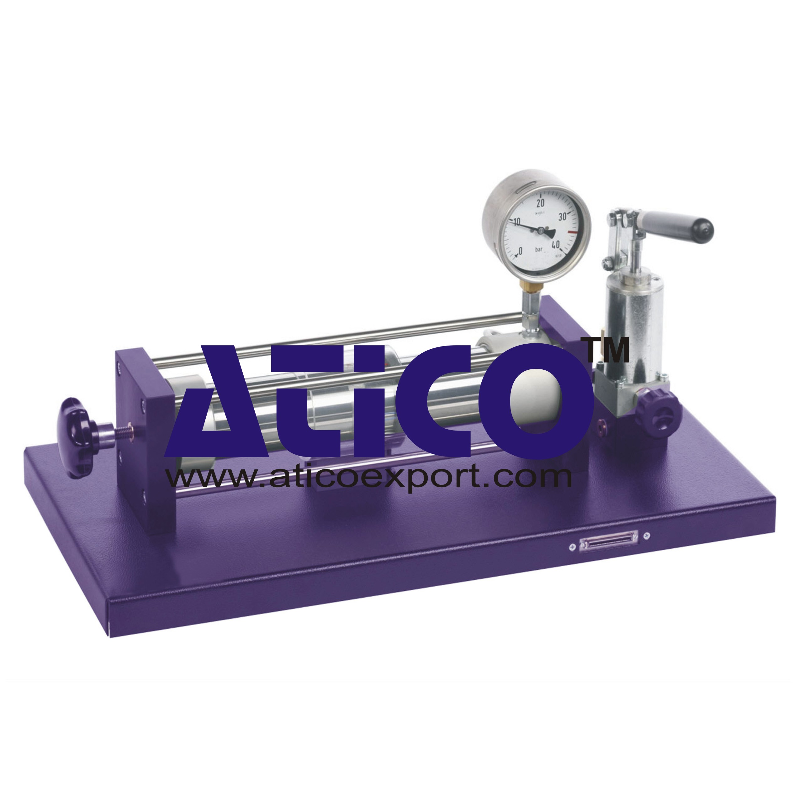
The findings obtained from the experiments using demonstrate the calculation and design methods for pipes and pressure vessels commonly applied in practice. The principal stresses are key variables in calculating and designing steam tanks, pressure vessels and pipes. The stresses and strains occurring in a vessel are not measured directly, but are determined by measuring the strains on the surface using strain gauges. The experimental unit is used to investigate stresses and strains in a thin-walled cylinder subjected to internal pressure. The oil-filled cylinder is closed at one end and a movable piston at the other end. This conveniently permits the unit to be either open or closed ended. A handwheel with a threaded spindle is used to move the piston. Two load cases are represented: biaxial stress state of a closed cylinder, such as a boiler tank, and uniaxial stress state of an open vessel, such as a pipe. Internal pressure is generated inside the cylinder by a hydraulic cylinder and a hydraulic pump. A pressure gauge indicates the internal pressure. Strain gauges are attached to the surface of the cylinder to record the strains. The measurement amplifier gives a direct readout of the measured strains. To assist and visualise evaluation of the experiment, the measurement data can be imported into the application software. Mohr’s Circle for stress and strain analysis is used to represent the conversion of the strain graphically and determine the principal strains. The principal stresses are calculated from the principal strains by applying the appropriate equations of elasticity. The well-structured instructional material sets out the fundamentals and provides a step-by-step guide through the experiments.
Specification:
1. Investigation of the stresses and strains in a thin-walled cylinder under internal pressure 2. Cylinder usable as open pipe or as closed tank 3. Strain gauge application on cylinder surface at various angles 4. Hydraulic cylinder with hydraulic pump to generate pressure 5. Hermetically sealed hydraulic system, maintenance-free 6. Multi-pin connector for measurement amplifier FL 151 providedTechnical Data:
Aluminium cylinder
- length: 400mm - diameter: d=75mm - wall thickness: 2,8mm - internal pressure: max. 3,5N/mm² (35bar)
Strain gauge application
- 5 strain gauges: half-bridges, 350 Ohm - angle to vessel axis: 0°, 30°, 45°, 60°, 90° - gauge factor: 2,00 +/-1% - supply voltage: 10V
Pressure gauge
- 0...40bar, accuracy: class 1,0
quick overview :
Stress and Strain Analysis Thin Walled Cylinder
Technical Description:
The findings obtained from the experiments using demonstrate the calculation and design methods for pipes and pressure vessels commonly applied in practice. The principal stresses are key variables in calculating and designing steam tanks, pressure vessels and pipes. The stresses and strains occurring in a vessel are not measured directly, but are determined by measuring the strains on the surface using strain gauges. The experimental unit is used to investigate stresses and strains in a thin-walled cylinder subjected to internal pressure. The oil-filled cylinder is closed at one end and a movable piston at the other end. This conveniently permits the unit to be either open or closed ended. A handwheel with a threaded spindle is used to move the piston. Two load cases are represented: biaxial stress state of a closed cylinder, such as a boiler tank, and uniaxial stress state of an open vessel, such as a pipe. Internal pressure is generated inside the cylinder by a hydraulic cylinder and a hydraulic pump. A pressure gauge indicates the internal pressure. Strain gauges are attached to the surface of the cylinder to record the strains. The measurement amplifier gives a direct readout of the measured strains. To assist and visualise evaluation of the experiment, the measurement data can be imported into the application software. Mohr’s Circle for stress and strain analysis is used to represent the conversion of the strain graphically and determine the principal strains. The principal stresses are calculated from the principal strains by applying the appropriate equations of elasticity. The well-structured instructional material sets out the fundamentals and provides a step-by-step guide through the experiments.
Specification:
1. Investigation of the stresses and strains in a thin-walled cylinder under internal pressure 2. Cylinder usable as open pipe or as closed tank 3. Strain gauge application on cylinder surface at various angles 4. Hydraulic cylinder with hydraulic pump to generate pressure 5. Hermetically sealed hydraulic system, maintenance-free 6. Multi-pin connector for measurement amplifier FL 151 providedTechnical Data:
Aluminium cylinder
- length: 400mm - diameter: d=75mm - wall thickness: 2,8mm - internal pressure: max. 3,5N/mm² (35bar)
Strain gauge application
- 5 strain gauges: half-bridges, 350 Ohm - angle to vessel axis: 0°, 30°, 45°, 60°, 90° - gauge factor: 2,00 +/-1% - supply voltage: 10V
Pressure gauge
- 0...40bar, accuracy: class 1,0
Product
Reviews
add Review
reviews
No Review Yet.





Product
Reviews
add Review
reviews
No Review Yet.