Wind Tunnel For Boundary Layer Experiments
Categories: Mechanical Lab Equipment ManufacturerWind Tunnel For Boundary Layer Experiments Teaching objectives of Wind Tunnel For Boundary Layer Experiments The following experiments may be carried out with or without a constant temperature anemom...
Product
Description
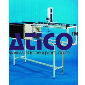
Wind Tunnel For Boundary Layer Experiments
Teaching objectives of Wind Tunnel For Boundary Layer Experiments The following experiments may be carried out with or without a constant temperature anemometer.- Boundary layer growth in the case of a two-dimensional wall jet.
- Measurement of velocity profiles.
- Measurements in laminar and turbulent boundary layers .
- Establishment of a dimensionless profile and invariants.
- Determination of the local skin-friction coefficient.
- Studies of mass and momentum flows, determination of dimensionless coefficients.
- Additional experiments which can be carried out with a constant temperature anemometer .
- Hot wire anemometer calibration.
- Verification of King's law.
- Effects of probe angle relative to the main stream velocity direction.
- Introduction to measurements in turbulent flows.
- Measurements of turbulent intensity in a free jet and in a boundary layer.
- Measurements of turbulence spectra for different Reynolds numbers.
Technical specifications
A centrifugal fan is mounted inside a settling chamber, of 0.25 sq.m cross-section, which is fitted with an interchangeable filter, an anodised aluminium honeycomb flow straightener, and a bronze screen to lower the turbulence level.
- A plexiglas two-dimensional contraction, with a contraction ratio of 30, ensures good flow distribution at the jet exit.
- A simple mechanical by-pass system on the chamber wall is used for progressive and accurate control of the jet exit velocity up to 25 m/s.
- The jet is confined by two vertical side-walls constructed in plexiglas. One of the panels is hinged and can be lowered to allow access to the test section.
- The traversing gear can be displaced along the entire length of the test section by means of a carriage mounted on linear ball races, which can be locked in position. Probe position is given by a pointer on the carriage and a scale on the test section.
- The traversing gear is designed to allow vertical displacement of the probe along the centre-line of the test section. Vertical position is determined by means of a vernier to within 0.01 mm. Fixtures permit the use of interchangeable probes of different diameters.
- A boundary layer probe available as standard.
- Motor rating: 230 W.
- Jet velocity: up to 25 m/s.
- Nozzle width: 300 mm.
- Nozzle height: 10 mm
- Total head probe.
- Pitot tube.
- Projection micro-manometer, resolution 0.2 mm water column.
- Hot wire anemometer and probes.
Dimensions and weight
- 2300 x 590 x 1760 mm (L x W x H) - 50 kg
Essential requirements
- 220V - 50 Hz, other voltages available on demand
quick overview :
Wind Tunnel For Boundary Layer Experiments
Teaching objectives of Wind Tunnel For Boundary Layer Experiments The following experiments may be carried out with or without a constant temperature anemometer.- Boundary layer growth in the case of a two-dimensional wall jet.
- Measurement of velocity profiles.
- Measurements in laminar and turbulent boundary layers .
- Establishment of a dimensionless profile and invariants.
- Determination of the local skin-friction coefficient.
- Studies of mass and momentum flows, determination of dimensionless coefficients.
- Additional experiments which can be carried out with a constant temperature anemometer .
- Hot wire anemometer calibration.
- Verification of King's law.
- Effects of probe angle relative to the main stream velocity direction.
- Introduction to measurements in turbulent flows.
- Measurements of turbulent intensity in a free jet and in a boundary layer.
- Measurements of turbulence spectra for different Reynolds numbers.
Technical specifications
A centrifugal fan is mounted inside a settling chamber, of 0.25 sq.m cross-section, which is fitted with an interchangeable filter, an anodised aluminium honeycomb flow straightener, and a bronze screen to lower the turbulence level.
- A plexiglas two-dimensional contraction, with a contraction ratio of 30, ensures good flow distribution at the jet exit.
- A simple mechanical by-pass system on the chamber wall is used for progressive and accurate control of the jet exit velocity up to 25 m/s.
- The jet is confined by two vertical side-walls constructed in plexiglas. One of the panels is hinged and can be lowered to allow access to the test section.
- The traversing gear can be displaced along the entire length of the test section by means of a carriage mounted on linear ball races, which can be locked in position. Probe position is given by a pointer on the carriage and a scale on the test section.
- The traversing gear is designed to allow vertical displacement of the probe along the centre-line of the test section. Vertical position is determined by means of a vernier to within 0.01 mm. Fixtures permit the use of interchangeable probes of different diameters.
- A boundary layer probe available as standard.
- Motor rating: 230 W.
- Jet velocity: up to 25 m/s.
- Nozzle width: 300 mm.
- Nozzle height: 10 mm
- Total head probe.
- Pitot tube.
- Projection micro-manometer, resolution 0.2 mm water column.
- Hot wire anemometer and probes.
Dimensions and weight
- 2300 x 590 x 1760 mm (L x W x H) - 50 kg
Essential requirements
- 220V - 50 Hz, other voltages available on demand
Product
Reviews
add Review
reviews
No Review Yet.






Product
Reviews
add Review
reviews
No Review Yet.